
“This changes everything”
Alexey Chekurkov changed the way my team looked at solutions for an operable OTC-X1 design. In mid 2018, things shifted into high gear for me. The Universe started delivering everything we needed, rapidly. It was an exciting time. More and more information and resources started flowing in. Synchronistic events lead to acquiring what was needed.
Then, as some of you are aware, we slammed the brakes on everything. I’ve said nothing about why. I walked away, leaving my hacked website a mess. In time, perhaps in the near future, I’ll share the details. Until then, I’ll say that we got some help from on high, and we were hindered, as well.
OTC-X1 Flying Saucer by Walter Nowosad | Redbubble
January 2022 Design Details
APEC Graviflyer video posted January 2022
Google docs answer many questions we had back in 2018.
Archive from 2018
Keep in mind that this section is archived from my old website. It represents a point in time where we didn’t have complete design details and were trying to figure it all out. The links above fill in the blanks.
The Flight of Gravity (Полёт Гравилёта)
An outdoor demonstration
Flight of the Gravillet, Exposure (Полёт Гравилёта, Разоблачение)
Outdoor demonstration of a levitation device with English captions proving it’s real.
Take-off and landing of the disc (answers to questions) – Взлёт и посадка диска (ответы на вопросы)
Alex Flying Craft (Полёт Гравилёта)
An English language interpretation and analysis of Alexey’s Device. This video provides close-up views of electrical connections.
Fifth launch of the gravity plane, (Пятый запуск гравилёта)
Graviflier Schematics
The gravity scheme and theory of levitation, (Схема гравилёта и теория левитации)
Schematics for the Alexey Device have been released in this 40-minute video. It’s in the Russian language, features English subtitles, and the schematics are readable. Here is a text file English translation of this video that was sent to me shortly after the video was posted. I’ve not compared it to YouTube’s subtitles. I suspect my version may be more accurate.
Observations and questions about Alexy’s Graviflier schematic
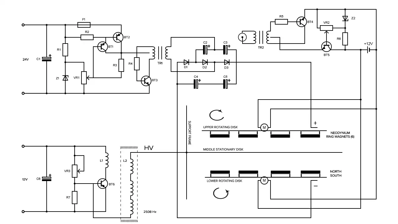
Pictured above is my recreation of Alexey’s Electrical schematics, which was based Alexy’s pencil drawing. I’ve omitted component values and their units-of-measure from the diagram; because his labeling was either unclear and difficult to read, or altogether missing. Let’s get into the details of each component.
MOTORS
There are two electric motors. Based on the videos, they appear to be lightweight pancake motors akin to computer cooling fans. The lower motor could be a repurposed bathroom ventilation fan.
CAPACITORS
All capacitor symbols are electrolytic capacitors. No values were specified, making it impossible to rebuild it. It was difficult to read the polarity for C2. If the circuit is supposed to be energized with AC, then the wrong capacitor symbol was used.
C1, C2, C3, C4, C5 – No values specified
C6 – 2200. A set of letters follow the numerals, which don’t seem to align with capacitor values. Capacitance’ standard unit of measure is ‘f’ for Farads. This capacitor could be μf (micro Farads), or other. I just don’t know.
DIODES
For D1, D2, and D3, no part numbers are specified.
RESISTORS
The standard unit of measure for resistance is Ohms. Its symbol is the omega — Ω. The few resistors sporting values were relatively easy to read; however, not all resistors included Ω, KΩ, MΩ, etc. so, I omitted values from the drawings.
R1, R2, R3, R4, R6 — No values specified
R5 – Alexy has written what appear to be 1000H (it looks like a letter ‘H’, not an omega). If it is supposed to be an H, then the wrong symbol has been used. H stands for Henries, which is the standard unit of measure for an inductor (or coil). Alternately, it could be 1000M, which represents 1,000,000,000 Ω. The 1000M resistor I found online is vintage.
R7 — The marking appears to be 47n. Again, this does not look like an omega. Can we assume it’s 47 Ohms?
VARIABLE RESISTORS
VR1 – It’s either 5KΩ or 51KΩ. It’s tough to read.
VR2 – no value specified
VR3 – 10K Ω
BIPOLAR TRANSISTORS![]() The schematic contains six bipolar junction transistors, a mixture of p-n-p and n-p-n. Two numbers appear near BT3 (an n-p-n type) at the base of the Tesla coil’s L2. One is a Russian transistor part number (KT819) and the other number – 250843 – could either be read as 2508Hz or 250843.
The schematic contains six bipolar junction transistors, a mixture of p-n-p and n-p-n. Two numbers appear near BT3 (an n-p-n type) at the base of the Tesla coil’s L2. One is a Russian transistor part number (KT819) and the other number – 250843 – could either be read as 2508Hz or 250843.
The three characters around BT3 are likely Cyrillic letters labeling each transistor lead: emitter, base and collector. The ‘k’ at BT3 being the collector, rather than cluing a possible value for coil L1 connected to it.
During the team’s Skype call, we discussed this drawing and Tesla Coil voltages. They concluded 250843 roughly represents 250 kV or 250 kHz. Two more Russian transistor part numbers KT838 and KT 815 appear near the emitter of BT3 and under transformer TR1.
This website shows their equivalent Western part numbers. Transistor data sheets for each is linked, below. I was unable to locate a Western equivalent for KT838 and discovered some of the transistors to be obsolete.
RUSSIAN PART NUMBER / WESTERN EQUIVALENT PART NUMBER
KT838; KT38A / UNKNOWN western equivalent
KT815 / BD165 western equivalent
KT819 (Same as KT 818G, but with n-p-n structure) / BDY20, BDY23 western equivalent
BT1 – p-n-p bipolar junction transistor
BT2 – p-n-p bipolar junction transistor
BT3 – n-p-n bipolar junction transistor
BT4 – n-p-n bipolar junction transistor
BT5 – n-p-n bipolar junction transistor
BT6 – p-n-p bipolar junction transistor
VOLTAGE SOURCES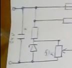 The voltage values scribbled on the left could be 24V and 12V – can’t say for sure. The flavor of waveform Alexey applies is not specified; however, given images appearing in his video, the Tesla Coil L1 may be receiving a square wave from a switching power supply.
POWER SUPPLIES AND “KATCHER”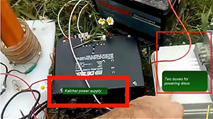
Throughout the video and in the comments section, I see repeated references to the “Katcher”. My best guess is that the power supply and circuit feeding the Tesla Coil is the “Katcher”. In fact, you’ll find imprinted on the black box “Switching Power Supply”.
12 V STARTER BATTERY Alexey says, “…and this lead is only powering high-voltage power supply”.
His schematic indicates two sources of high voltage from two different power supplies. Perhaps the 12 V Starter Battery is feeding the two white boxes. The caption reads, “Two Boxes for powering discs”.
We are unable to see all sides of them to determine how they’re interconnected. What’s contained inside is unknown.
Later, the video shows Alexey disconnecting a white lead from the 12V / 44 Ah / 360 CCA starter-battery. The video whip-pans to reveal his Gravifier hovering in the sky for several seconds until it deenergizes and drops to the ground.
Source voltage values are difficult to identify from Alexey’s pencil drawing. I may have incorrectly interpreted the top left source to be 24V. Should it be a 12 VDC starter battery? Is the starter battery the sole source of power for all three circuits?
- Two motors & a piezoelectric ultrasonic sound generator sharing one circuit
- One Tesla coil primary feeding stepped-up high voltage via its secondary to the center fixed disc; and,
- A “magnifying” circuit which energizes the rotating plates
LIGHTNING ARRESTOR (SPARK GAP) ON A DC CIRCUIT
![]() What is the purpose of the circuit that contains transformer TR2? What is the function of the spark gap connected to TR2’s secondary, when its primary is energized with a 12 VDC from a Battery?
What is the purpose of the circuit that contains transformer TR2? What is the function of the spark gap connected to TR2’s secondary, when its primary is energized with a 12 VDC from a Battery?
My friend, who translated Alexey’s Russian, says this circuit powers a piezoelectric ultrasonic sound generator. When the sound interacts with the “special metal” (textured metal), you have levitation. The sound of a beetle’s beating wings interacts with the rough under-texture of its wing covers, which levitates the bug; so, the special metal – rough, textured, and bumpy – represents the beetle’s rough under-surface, and the ultrasonic sound generator represents the beetle’s vibrating wings. This is Alexey’s nod to Viktor Grebennikov. Alexey doesn’t say what kind of metal it is or where it came from.
ULTRASONIC SOUND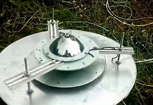 The ultrasonic sound generator is most likely physically positioned above the top motor and hidden under what appears to be a plastic dome, which could be a reflector scavenged from a large flashlight.
Could the dome we see on top be an inverted ultrasonic piezo speaker? I searched the Internet and found several; but, none of them resembled Alexey’s dome. Except for the schematic symbol appearing in his drawing to clue us into it being an ultrasound speaker, we simply don’t know what’s underneath.
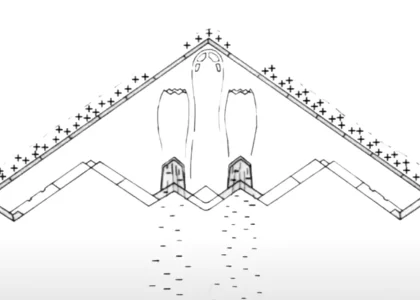
 Could the Alexey device operate on sound alone? If so, could it operate in a vacuum? Not likely. What else could be used in place of sound – perhaps UV light, as suggested by William R. Lyne in his book, Pentagon Aliens, 3rd Edition? Note the external arching waves (left), analogous to sound waves – are these U.V. light resonators?
According to my Russian-English interpreter friend, Alexey says the device’s voltages, frequencies, and ultrasonic sound must be in resonance.
SPECIAL METAL
in the video below, Alexey says he uses “special metal”. It’s considered special because it’s textured.
One of our engineers recommended William R. Lyne’s book, Pentagon Aliens, 3rd Edition – and I can’t put it down.
In it, he mentions quilted aluminum, which apparently was the crisscross ridge patterns of early stealth technology developed by the Germans during for their WWII U-boats, and, if you believe the story about German WWII flying saucers, this material was then adapted to their saucer designs. Friends of the author described seeing this pattern on UFOs.
This brings Alexey’s special metal to mind. A few seconds on Google; and, voilà! I find rigidized metal: Some suppliers call it Stucco metal.
Overview of the Mysterious Properties of the Metal Gravity
Russian to English transcript of above video: “Overview of the Mysterious Properties of the Metal Gravity”.
 I’ve overlaid a closeup image of Alexy’s Graviflier’s special metal with Rigdized Metals’ 1SLG sample. They look similar. According to Rigidized Metals website, this texture is available in stainless steel and other metals.
COPPER SLIDING CONTACTS (BRUSHES)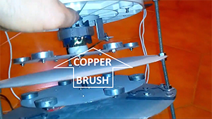 The sliding contacts (a strip of copper) provide a conductive path to carry a single-polarity high-voltage pulsed charge to the spinning discs (positive on the top disc; and negative on the bottom disc).
How much voltage should the brushes be feeding the upper and lower rotating discs? According to my friend who performed the first rough translation of Russian to English says the circuit following Transistor TR1’s secondary “magnifies”.
MAGNETS
Alexey’s drawing shows magnets mounted to one disk only; but the device appearing in the videos shows magnets mounted to both discs. My drawing includes magnets on both. I assume north poles face each other. This may be incorrect. The functional purpose of the magnets is unknown. Perhaps the counter-spinning plates would create a vortex of electric and magnetic fields to isolate the device from Earth’s gravity? This is a guess, speculation that came about during a conversation with an engineer. Alexy explains dual vortexes working together.
POLARITIES – ELECTRIC CHARGE AND MAGNETIC POLES
While he admits he may not be using the right words in his explanation, Alexey rationalized the lower spinning disc should be negatively charged ~ to Earth. He continues by describing vortex fields spinning upward and downward from the rotating disks, which excludes it from Earth’s gravity; but he stops short of describing the magnets’ orientation.
HIGH VOLTAGE CHARGES
The middle stationary plate – charged by the Tesla coil – may act as an electric barrier to separate opposite-spinning toroidal fields created by counterrotating high-voltage-charged upper and lower plates. One of our team members speculates its purpose may be to prevent the opposing polarities and fields (electric and magnetic) from mixing and neutralizing. Alexey says everything must be in resonance – all three charged plates and the ultrasonic sound (vibration).
TWO DEVICES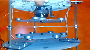 Alexey features at least two devices on his YouTube channel. The one pictured here is not the same one used during his indoor and outdoor video demonstrations. It is smaller in diameter, lighter weight; and the discs are not made from a “special metal”. According to my translator, they’re CDROM discs!
At the time Alexey recorded the schematics video, this device was still in construction. Both discs appear opaque, as if coated with something; yet, in a higher camera angle; the disc appears to be transparent. Is this a trick of light and shadow?
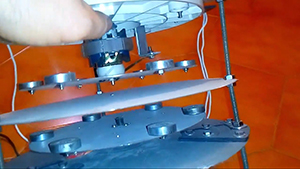
 With a copper contact in direct contact with the upper and lower rotating CDROM discs. We speculated the foil aluminum encased in the layers of polycarbonate may interact with the high voltage charge.
Since the copper brush is not in direct contact with a conductive plate, assuming the disc is not coated or sprayed with conductive materials and the only conductor present would be sandwiched between 1.2 mm of polycarbonate plastic (an insulator); and if the goal is to apply a high voltage charge to the extremely thin layer of embedded aluminum, we have to turn our attention to breakdown voltage of 1.2 mm thick polycarbonate material. How will the embedded aluminum react to the pulsed charge? Will it heat up, expand, and cause the disc to come apart?
 The upper rotating disc appears to be transparent from the high camera angle. If you’ve ever purchased sleeves of CDs or DVDs, you’ll know they ship with a clear plastic packaging insert at the top and bottom of the sleeve, which does not contain aluminum. Is that what Alexey is using here? If so, how will the rotating polycarbonate plastic discs receive a high voltage charge?
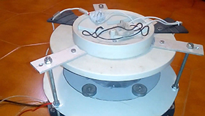
WIRING AND ELECTRICAL ISOLATION
A set of black and white wires and connection blocks are on top. The piezoelectric ultrasound device is absent. These four wires could be feeding power to both motors and the Piezoelectric Ultrasonic Sound Generator. Note the black triangles bolted to the lower stationary plate. Could they be insulators electrically restricting the high voltage charge to the center stationary disc?
WHAT’S NEXT?
Alexey says his next video will show how he tunes the circuits. As mentioned in another video, it takes Alexey thirty to sixty minutes to tune the device. During my Russian to English translation session, I also got this: Too much high-voltage can prevent levitation. Who knows what other variables factor into tuning?
WAVE FORMS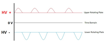 My team discussed wave forms, such as a pulsed half-wave riding on an offset DC signal – positive polarity at the upper and negative polarity at the lower. The waveform could be square, sin, or other. It could be in or out of phase. We simply don’t know.
We think the signals at all three plates receive some flavor of pulsed DC.
Power source voltage values are unclear.
We pondered how Alexey’s circuit, as drawn, would be tuned for resonance and adjusted to ascend and descend. All we have is speculation.
Based on his schematic, it appears voltage and current values are the only adjustable variables. VR1 would be adjusted to modulate current. My transistor knowledge is a little fuzzy; but, as I recall, depending on how the transistor is biased, changes in current and/or voltage affects frequency – the relationship may be inversely proportionate – as current increases, frequency decreases; and as current decreases, frequency increases. The amplitude of the signal varies with adjustments, as well; not to mention, the transistors would have to be capable of accommodating certain voltages, current, frequencies, etc.
We pondered, what’s missing? Is Alexey hiding something? Is he concealing other control knobs or circuits? Suggested as workaround to his circuitry: Rather than constructing your own Tesla coils, buy one off-the-shelf. For your High Voltage source leading to the rotating plates, it was suggested a neon sign transformer and Variac – to enable tuning – could be used.
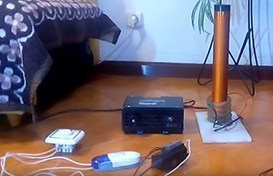 We attempted to identify electrical components appearing in one of Alexey’s previous videos. As shown here, there are four boxes – a black-colored metal box referred to as a “Katcher” (also known as a switching power supply) that apparently drives his Tesla coil; a white thing sporting a large dial (a dimmer / potentiometer (pot / variable resistor); a white and blue plastic thing; and a “throwback” (I think that’s what it’s called), which was likely liberated from an old television. How Alexey interconnected them to and “tuned” his Graviflier remains unclear.